Seismic-Vibration-EOR Lab
The research team supervised by Dr. Dai has been working in the application of vibration excitation technique on Enhanced Oil Recovery (EOR) process for the past years. The findings of the research team contribute substantially to the areas of comprehension of the EOR with vibration stimulations, wave propagations in porous-media of oil field, and multiphase liquid mobilization in porous-media.
Seismic-Vibration-EOR Lab is established since 2004, it is mainly focus on the dynamic research of multi-phase flow in pore structure of porous media. A micro flow system is established to discover the mechanism of oil production in porous media underground; the experiment is developed for both statics and dynamics conditions, the flow behavior of oil slug in waterflooding process is obtained and analyzed. The major components include: Microcell board, Stereo microscope, Vibration exciter, Syringe pumps, etc.
Following are the experiments involved in this lab.
- (1) Micro flow system
-
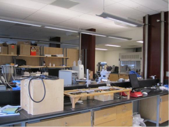
Figure 1 A corner of Seismic-Vibration-EOR Lab
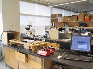
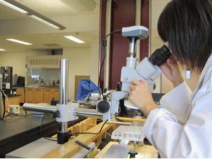
Figure 2 Establish of micro flow system to discover the mechanism of waterflooding process with vibration excitation
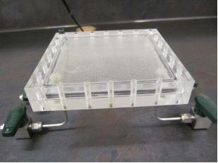
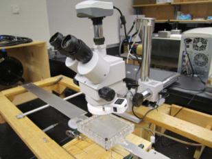
Figure 3 The optical system and micro cell in micro flow system
(2) Experimental and numerical research with pore structure flow system
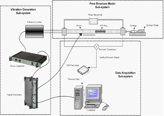
Figure 4 Schematic of dynamic experimental setup
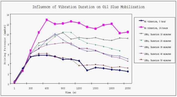
Figure 5 Influence of vibration duration on oil slug(20mm) mobilization
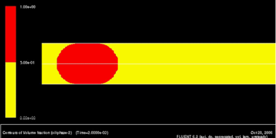
Figure 6 Numerical model of the micro flow system
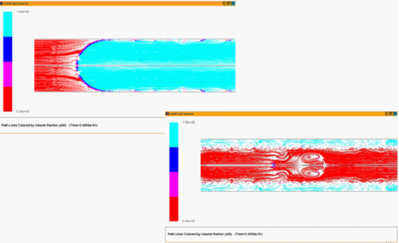
Figure 7 Mobilization oil slug under static condition-streamline
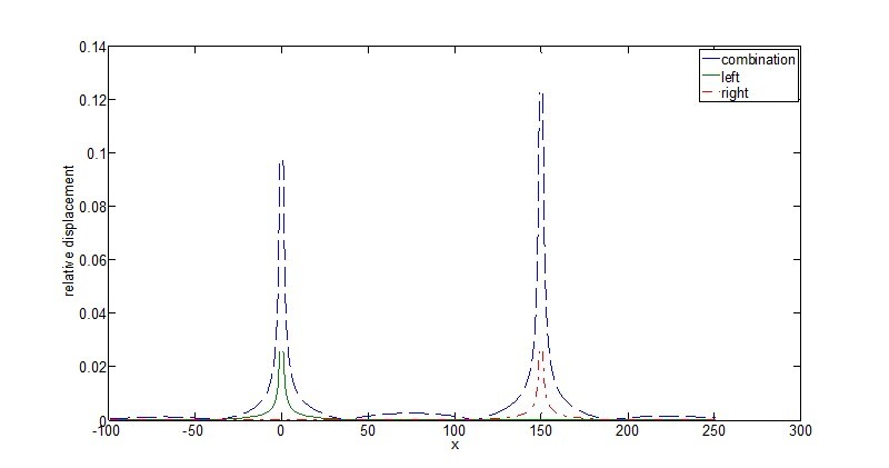
Figure 8 The relative displacements along the connecting line at a given time with viscous fluid under two energy sources
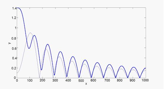
Figure 9 Comparison between the single (thin line) and two energy sources (thick line) in terms of relative displacement at a given time t= 400s in non-viscous fluid, multiple sources (0,0,0), (200,0,0), and single source (100,0,0) (unit in z-axis:![]() m)
m)
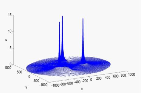
Figure 10 Maximum relative displacements caused by compressive wave on the plane containing three energy sources (unit in z-axis:![]() m) with non-viscous fluid
m) with non-viscous fluid
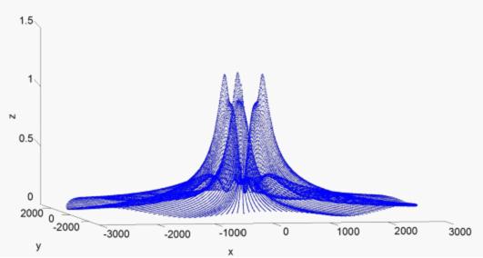
Figure 11 Maximun relative displacements caused by compressive wave in a plane 500m away from the sources plane (unit in z-axis:![]() m) with non-viscous fluid
m) with non-viscous fluid
Animations